Arches
The arch has long been used in masonry structures. In fact, a brick masonry arch found in the ruins of Ur in Mesopotamia dates back to 1400 B.C. Today, the brick arch is used in construction to span over wall openings and add aesthetics, as the arch is the consummate definition of form and function. This Brick Brief addresses design considerations for brick arches in veneer construction. Common arch terminology is shown in Figure 1. The first important consideration when designing a brick arch is whether the arch is structural or non-structural. That is, will the arch be required to transfer vertical loads to abutments or will it be fully supported by a steel angle. While this may seem obvious, confusion often develops because of the many configurations of arch construction.
Introduction
The arch has long been used in masonry structures. In fact, a brick masonry arch found in the ruins of Ur in Mesopotamia dates back to 1400 B.C. Today, the brick arch is used in construction to span over wall openings and add aesthetics, as the arch is the consummate definition of form and function. This Brick Brief addresses design considerations for brick arches in veneer construction. Common arch terminology is shown in Figure 1.
The first important consideration when designing a brick arch is whether the arch is structural or non-structural. That is, will the arch be required to transfer vertical loads to abutments or will it be fully supported by a steel angle. While this may seem obvious, confusion often develops because of the many configurations of arch construction. To answer this question, one must consider the two structural requirements necessary for a brick arch to adequately carry vertical loads. First, vertical loads must be carried by the arch and transferred to the abutments. Second, vertical load and lateral thrust from the arch must be resisted by the abutments. If either the arch or the abutment is deficient, the arch must be considered as non-structural and the arch and its tributary load must be fully supported by a steel angle or plates. Alternately, reinforcement may be used to increase the strength of either or both the arch and the abutments.
Structural Arches
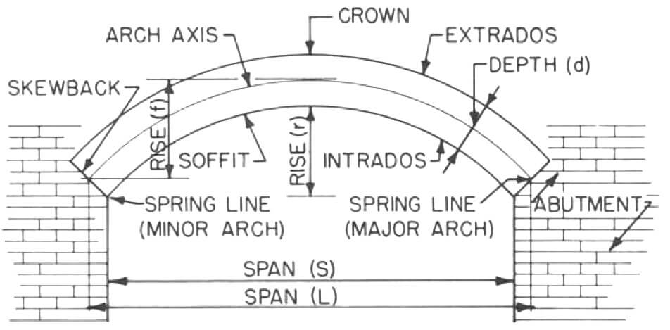
Figure-1.-Arch-Terminology
Technical Notes 31, 31A and 31C address the structural design of brick masonry arches. Design methodology and example calculations are provided for jack, segmental and semi-circular arches. The reader should refer to these Technical Notes for specific design recommendations. This Brick Brief discusses structural arch design requirements with respect to common arch problems.
The Arch. There are three failure modes of an unreinforced brick arch: rotation of the arch about the abutment, sliding of the arch at the skewback, and crushing of the masonry. Rotation occurs when tension develops in
the arch. Tension can be reduced by increasing the depth or rise of the arch. If tension develops in the arch, reinforcement can be added to resist the tensile forces. Sliding of the arch will depend on the angle of skewback (measured from horizontal) and the vertical load carried by the arch. Reinforcement can be added to avoid sliding at the skewback, as the reinforcement acts as a shear key. Crushing will occur when compressive stresses in the arch exceed the compressive strength of the brick masonry. If compressive stresses are too large, the arch must be redesigned with a shorter span or a greater arch depth. Compression failure seldom occurs.
The Abutment. An abutment is typically a column, a wall, or a combination of wall and shelf angle. If a shelf angle is used to abut the arch, the shelf angle must be attached to a non-combustible material. Failure of an abutment occurs from excessive lateral movement or exceeding the flexural, compressive or shear strength of the abutment.
Lateral movement of the abutment is due to the horizontal thrust of the arch. This thrust develops in all arches except a catenary arch. The flatter the arch, the greater the horizontal thrust. This thrust must be sufficiently restrained so that lateral movement of the abutment does not cause cracking in the arch or its collapse.
A common lateral movement problem found in residential construction occurs when a porch arch spans between columns. These columns are often constructed of solid brick masonry or wood studs with brick masonry surround. The column is typically designed based on axial load requirements, overlooking horizontal arch thrust. The arch thrust causes the column to deflect laterally resulting in collapse of the arch. The solution to this problem is to stiffen the columns, provide an adjacent wall, or provide a tie between the columns.
Non-Structural Arches
Non-structural arches require support by other elements. Many arches used today are non-structural, built purely for aesthetics. Structural support of the arch may be required because of insufficient arch or abutment strength or the lack of a structural analysis of the arch. Support is provided by a lintel which spans the opening or by a shelf angle which is attached to non-combustible materials. Design recommendations for steel lintels are given in Technical Note 31B.
Expansion Joints
Expansion joints in brick masonry can cause problems when arches are used in the building. Residential construction often does not require expansion joints because continuous wall runs are short. However, if an expansion joint is required near an arch, care must be taken not to affect the integrity of the arch. This is a common problem for very long arches or runs of multiple arches along column abutments.
Vertical expansion joints should not be placed in the area directly above a structural arch. This region of masonry is in compression, so an expansion joint would simply close, causing vertical deflection and possible collapse of the arch. Also, vertical expansion joints should not be placed in the abutment near the arch. This is because the expansion joint will allow lateral movement of the abutment due to arch thrust, possibly causing the arch to collapse. For the particular case of multiple arches closely spaced, vertical expansion joints should only be placed at the ends and at a sufficient distance away from the end of the arch span so that horizontal arch thrusts are adequately resisted.
Flashing
In residential construction, the presence of eaves, overhangs and small wall areas above openings will reduce the potential for water penetration at arch locations. However, flashing at an arch is just as important as over any other wall opening. Flashing an arch can be difficult, depending on the type of arch and the type of flashing material.
Jack arches are the easiest to flash because they are flat. Flashing may be placed below the arch on the window framing for structural arches or above the steel lintel for non-structural arches. Alternately, flashing may be placed in the mortar joint above the arch or keystone. Attachment of the flashing to the backing and end dams should follow standard procedures.
A segmental or semi-circular arch is more difficult to flash properly. This is because flashing materials such as metal flashings are very rigid and may be hard to work around a curved arch. See Brick Brief „ Stepped Flashing” for a detailed solution to flashing a segmental or semi-circular arch.
Construction Concerns
Both structural and non-structural arches must be properly supported throughout construction. Premature removal of the temporary support for a structural arch may result in a collapse of the arch. This is most often due to the introduction of lateral thrust on the abutment before proper curing has occurred.
Out-of-plane bracing is required for all arches. In veneer construction, it is provided by the backup material through the wall ties. Arches that are not laterally braced may require increased masonry thickness or reinforcements to carry loads perpendicular to the arch plane.
Arches may be constructed of special shapes or regular units. Mortar joints may be tapered with uncut regular units. Alternately, regular units may be cut to maintain uniform joint thickness. In general, use of speciallyshaped brick that result in uniform joint thickness will be more aesthetically pleasing. Many brick manufacturers offer such specially-shaped arch units.
Rules of Thumb for Veneer Arches
The following is a list of rules of thumb which may be used when designing structural veneer arches.
Jack Arches
- Six foot maximum span without a lintel.
- Larger skewback angle with longer span
- Skewback = 1/2 in. per ft (4 mm per 100 mm) of span for each 4 in. (102 mm) arch depth
- Camber of 1/8 in. per ft (1 mm per 100 mm) of span
- Minimum arch depth of one unit length, not rowlock only
- Abutment length equal to: span length for one surface, 1/2 span length for two surfaces (see Fig. 2)
Segmental Arches (Less than half circle)
- Rise/span ratio between 0.15 and 0.5
- Make skewback angle as small as possible
- Increase arch depth for better performance
- Wall height above spring line at least 1.3 times arch radius
- Abutment length equal to:
- 0.66 times span length for one surface
- 0.33 times span length for two surfaces (see Fig. 2)
Semi-Circular Arches (Half circle)
- Arch depth as small as 1/2 brick length
- Wall above should be at least (0.9)(Span) from spring line
- Abutment length equal to:
- 0.4 times span length for one surface
- 0.2 times span length for two surfaces (see Fig. 2)
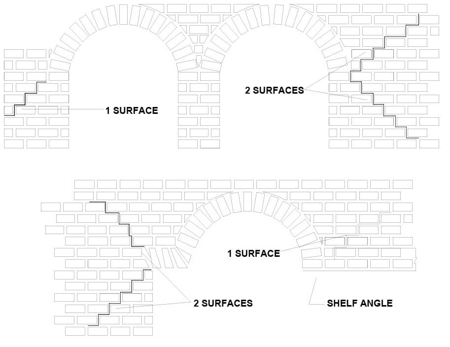
Figure-2.-Surfaces
Note: In order to qualify as two surfaces, the abutment must extend up to the crown of the arch. Also, combination wall and steel angle abutments have only one surface.
Brick Briefs are short discussions of a particular topic. The information contained herein is based on the experience of Brick Industry Association technical staff and must be used with good technical judgment. Final decisions on the use of this information must rest with the project designer and owner.